|
|
LSAM > The Process
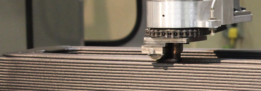
Unique bead compression wheel fuses layers together producing an accurate void-free structure
The Process
Beginning
The process begins with the creation of a 3D computer model. This computer model is processed using special software to create a print program. This program is used to print the part using the print gantry of the LSAM machine
The 3D computer model is also used to generate a CNC program to trim the printed part to the final size and shape. After the printed part has cooled this CNC program is used to machine the part to size using the trim gantry of the LSAM machine.
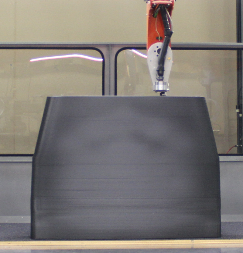
The printing process consists of heating thermoplastic material until it is soft and pliable and then laying it down as a continuous bead, layer by layer, until the part shape has been generated. Each new layer fuses with existing layers to produce a solid, strong, void free part.
The pelletized thermoplastic material is first dried to remove any moisture and then pneumatically conveyed to a vertically mounted print head. The print head heats the material to a softened state and meters the material at a precise controlled rate through a print nozzle. This advanced print head design automatically coordinates with machine motion to maintain precise print bead dimensions, even at very high print rates. It can also change print bead dimensions during the print process as needed.
LSAM uses a bead compression wheel to shape and flatten the extruded bead and fuse it with existing layers. This wheel is servo controlled to automatically follow machine motion.
Trimming
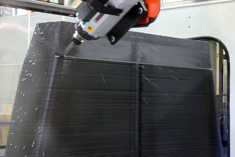
Trimming is accomplished using a five axis CNC router mounted on a separate 5 axis trim gantry which rides on the same overhead rails as the print gantry. It uses a 12 HP, 3000 to 24,000 RPM automatic tool change spindle with a ten position automatic tool changer.
The vertical Z axis stroke is a foot higher than the maximum print height, so that the router head can machine from the print table surface to a point completely over the top of a printed part. The trim gantry is also equipped with an automatic tool length measurement system and Thermwood’s patented impact resistant head. The machine uses Siemens Intelligent Servo Drives throughout, including the print head drives.
Software
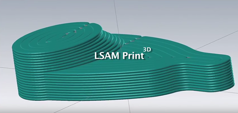 The process starts with a 3D computer model of the part. This design, in an industry standard solid, surface or mesh file format, is loaded into Mastercam software. Thermwood’s LSAM Print3D software utility, which operates within Mastercam, is used to generate the CNC print program needed to print the part using the print gantry. Both a working copy of Mastercam and Thermwood’s LSAM Print3D software utility are required to develop a print program.
The 3D computer model is then used to generate a trim program which is used to trim the part using the trim gantry.